Design Round - Synechdoche, Long Running Project

In the movie, Synechdoche, New York, a theatre director, embarks on a mission to create a magnum opus which mimics reality. In his pursuit, he creates a miniature version of every aspect of his life - from physical space to his relationships. As the production progresses, the warehouse resembles life outside, right to the lowest level of detail.
Not unlike the mission, in a technical design round, you’re expected to design a smaller scale version of the project. Soon enough, you’re faced to deal with the nitty-grittties of the project constraints. They crammed all this in an hour. Of course, the aim is to gauge how you approach the problem. A crucial aspect of the design interview is the technical architecture diagram. Sometimes, you’re judged on this artifact. When I took those interviews, I would wing the diagrams. Soon I realised it is important to give this a serious thought for any chance of success. Usually, the design round is split into two parts - low-level design and high-level design. What they call low-level design is the design of the domain model or the domain entities, and the high level design is about the components of the system - services.
Modeling the Domain Model #
You start the design by designing the entities. Identifying entities for the design domain is an art. (Applying UML and Patterns Larman, 2004) suggests these ways to identify the entities in the system:
Reuse or change existing models. There are well-crafted domain models and data models for many domains, like inventory, finance, health, and so forth. If the problem at hand sits well with the data models, then reusing the data models is a wonderful choice.
Map the domain to the existing models. If the problem can be modeled by mapping the domain to domains with well-crafted models, then make use of them.
Identify noun phrases. The noun phrases in the problem description suggest what domain models might come into play when designing the system. They can be candidates for the entities.
There is designing in the large and then there is designing in the small. Large-scale or enterprise-scale design make use of frameworks like the Zachman Framework which is a useful guideline when there are many designers working on the same problem. However, in the interview scenario, you are likely to come across a smaller slice of the problem. Small scale design guidelines like the Domain-driven design are a better fit in the small-scale design. In Domain-driven design, you carve out domain models and design a bounded context for them. DDD is useful for modeling with event-based architecture with CQRS pattern. Long and short - domain models are the gateway to your design. Design them well, and you’re well on your way to the next step - communicating your design using diagrams.
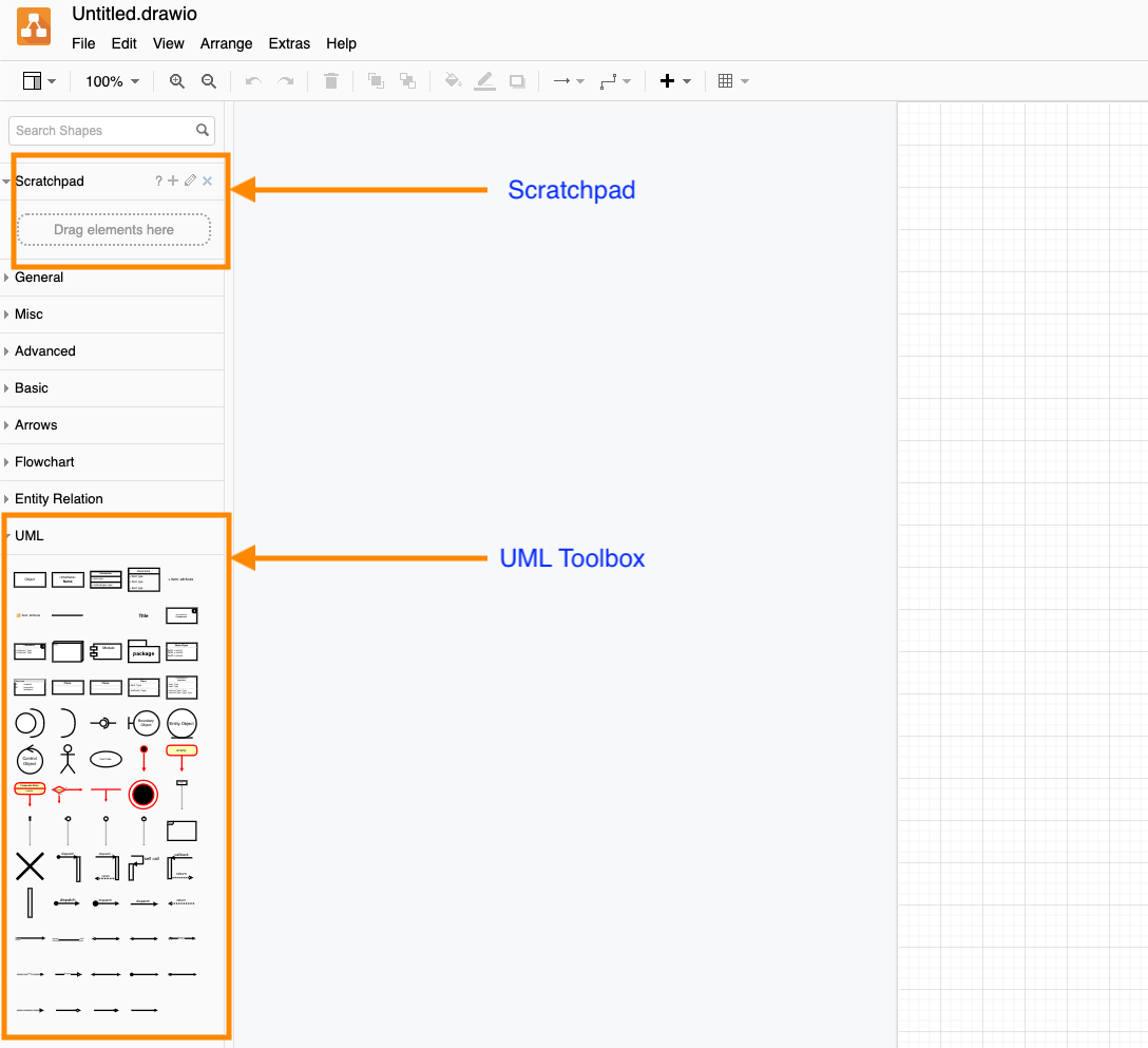
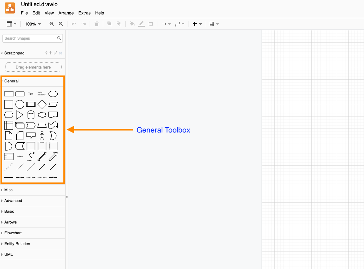
You can enumerate your model using a text editor, but it is a suboptimal way of conveying your design. UML is a well-known language for communicating the object models. With UML, you can show relationships, drawn object graphs and lay out your models visually. After laying out your visual dictionary, you will quickly start strongly. Because it is a well-known language, you will also save time in explaining the relationships. Also, it is an artifact that the interviewer can use to refer during any discussion. diagrams.net is an excellent online tool. In fact, most of the interviewers suggest you use it. The application has a drag-and-drop interface for designing UML diagrams, ER diagrams etc.
Now there are notations like SysML for describing the architecture, but unlike UML, they are not popular. So, how do we convey our dynamics of the system, “high-level architecture diagram”?
Modeling the Application Flow #
We can get a sense what is expected of us in the interviews by looking at the engineering blogs of the tech companies. For example, here is a blog article from Uber’s Engineering blog which has a “high-level diagram” of the architecture of one of its products - Uber’s Finance Computation Platform. The Architecture diagram from the blog is interesting - it has three major components - services, data stream topics, and data stores. Every component is labelled. The shapes of the components are simple - square boxes for services, conventional data store symbols for data stores. The arrows show the flow of data. We can call the diagram a data-flow diagram, but it succintly highlights the chief concerns of the system that they built. Event-based architecture with microservices is the pattern du jour; so in a majority of cases, the general expectation in the interviews is to design the architecture using those patterns. Not that this is the only architectural paradigm, and we should force-fit every design in that mold. For example, another focus in the interviews is how data is ingested and processed by the system. Interviewers look for the data flow in the design. If you are designing a system for large-scale data processing, whether streaming or batch, you are better off showing the processing using a data flow diagram. In the book, (Fundamentals of Software Architecture Richards & Ford, 2019), there is a rundown of architectural styles like Layered MVC architecture, Micro-kernel architecture, Space-based architecture, Event-based architecture, and Microservices architecture among others. The architecture diagram should support the design.
Sticking to simple rules of thumb might be a better option. This is because you are not sure of what works for the interviewer and what does not. For example, while UML is ubiquitous enough, SysML is not. So it is better to err on the side of not using SysML even though it might be more expressive at what you are trying to model. In the book, (Fundamentals of Software Architecture Richards & Ford, 2019), the authors provide general guidelines to use like making sure that the title should be used for disambiguating entities. The guidelines are listed here:
Title - Make sure that the titles are well known
Lines - Lines should be thick enough. Use arrows for showing traffic. One of the few standards is use solid lines for synchronous communication, and dotted lines for asynchronous communication.
Shapes - Well-known shapes, like the symbol for the database, are effective in expressing the intent. There aren’t any hard and fast rules for what shapes to use, but make sure that those are consistent. Use a legend for disambiguation.
Label - Label each item in the diagram.
If you’re using diagrams.net, then you can make use of the default toolset that has all the bells and whistles for making a simple high-level flow diagram.
Sketching is something that we all do from time-to-time. Technical architecture diagrams extend the idea, albeit on a formal level. Making these diagrams and getting good at them is a high leverage activity. As a developer, or a senior engineer, we make design documents. A detailed diagram supplements the narrative document. To borrow a phrase - a picture speaks a thousand words.
Summary #
Use UML for your low-level architecture diagrams.
Use, and get better at a tool like diagrams.net.
Start out your diagrams using simple symbols and label them.
Readings #
Larman, C. (2004). Applying UML and Patterns: An Introduction to Object-Oriented Analysis and Design and Iterative Development (3rd Edition). Upper Saddle River, NJ, USA: Prentice Hall PTR.
Richards, M., & Ford, N. (2019). Fundamentals of Software Architecture: An Engineering Approach. O’Reilly Media, Incorporated.